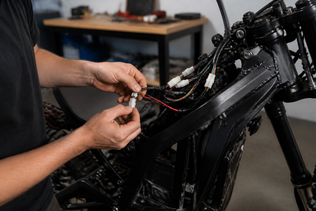
Table of Contents
- Surron Wiring Harness Replacement Tools
- Safety Precautions and Battery Disconnection
- Removing the Old Surron Wiring Harness
- Routing and Connecting the New Surron Wiring Harness
- Surron Throttle Wiring Color Code and Connector Mods
- Surron Light Bee Electrical Troubleshooting
- Waterproofing, Voltage Drop, and CAN-Bus Basics
- Conclusion
- Frequently Asked Questions
Last Updated: September 21, 2026
Surron Wiring Harness Replacement Tools
Learning how to install Surron wiring starts with the right tools, and most riders skip that step. At Moto X Industries, we see the same problem repeatedly: stripped connectors, cracked insulation, and a bike that won’t power on because someone used pliers instead of a crimper.
Essential Hand Tools and Test Equipment
A basic electrical tool set covers almost every job on a Surron harness:
- Digital multimeter for continuity, voltage, and resistance checks
- Wire strippers sized for 16-22 AWG wire
- Ratchet crimper for insulated and non-insulated terminals
- Soldering iron (60W or higher) with rosin-core solder
- Heat-shrink tubing in 2mm to 8mm sizes
- Zip ties and adhesive cable clips
- Socket set for body panels and battery tray bolts
- Nylon panel pry tools to release plastic clips without snapping them
Test your crimper on scrap wire before you start. Squeeze a test terminal, then pull hard on the wire. If it slips out, your crimper is set too loose. Fix that now, not after you’ve crimped twenty connections.
Safety Precautions and Battery Disconnection
Disconnect the battery before removing a single panel. A Surron pack holds serious current, and a live positive lead touching the frame can arc, melt insulation, or start a fire.
Follow this order every time:
- Power off the bike and remove the key.
- Unplug the main battery connector from the controller.
- Wait several minutes for capacitors to discharge.
- Verify zero voltage at the controller terminals with your multimeter.
- Work on a dry surface, away from fuel, solvents, or open flame.
Skipping the voltage check is the most common mistake we see. Capacitors can hold a charge after the battery is unplugged. If you start pulling connectors while voltage is still present, you can short the controller and destroy it in seconds.
Removing the Old Surron Wiring Harness
Photograph every connector before you unplug it. Your phone camera is the best wiring diagram you will ever have.
Work panel by panel, and label as you go:
- Tag each connector with masking tape and a number.
- Note the pin-out of any multi-pin plug before separating it.
- Trace each branch of the harness and mark where it clips to the frame.
- Cut zip ties rather than pulling them loose, so you don’t stress the wires.
Routing and Connecting the New Surron Wiring Harness
Route the new harness along the same path as the old one and secure it every few inches. Loose harnesses rub the frame, and vibration wears through insulation over time.
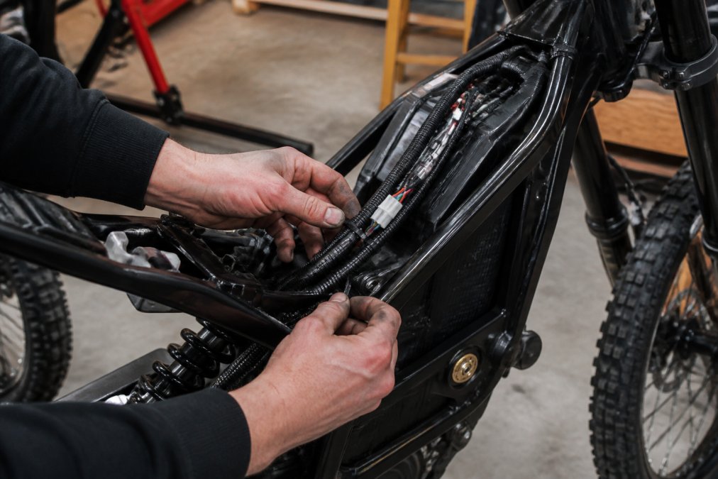
Controller, Motor, and Battery Connections
Match phase wires by color and confirm the pin-out before plugging anything in. Most Surron controllers use clearly marked phase and hall sensor plugs, but aftermarket parts vary.
- Phase wires: thick gauge, usually three, matched by color
- Hall sensor plug: thin multi-pin connector, keyed to fit one way
- Main battery leads: heavy gauge, bolted or plugged, polarity critical
- Ignition and kill switch: small two-pin connectors
Brake Sensor and Light Switch Integration
Brake sensors cut motor power when you pull the lever. Wire them so the signal reaches the controller, or the motor keeps pushing while you brake.
Surron Throttle Wiring Color Code and Connector Mods
Throttle wiring is where most home installs go wrong: the color code is a convention, not a guarantee. Two bikes from the same model year can ship with different harness suppliers, and aftermarket throttles rarely follow the factory palette. Confirm every wire with a meter before cutting or crimping.
What Each Throttle Wire Actually Does
A hall-effect throttle is a three-wire sensor plus, on some models, a fourth wire for the speed limiter. The controller feeds a regulated 5V reference, the throttle returns a signal voltage that rises as you twist, and the controller maps that voltage to motor current.
| Wire Color (typical) | Function | Meter Test | Expected Reading |
|---|---|---|---|
| Red | 5V reference from controller | DC volts, key on, probe red-to-black | 4.8-5.2V steady |
| Black | Signal ground | Continuity to battery negative | Near 0 ohms |
| Green | Wiper / signal output | DC volts while slowly twisting | Rises smoothly from ~0.8V to ~4.2V |
| Blue or White | Speed limit / mode wire | Continuity to ground when grounded | Closes to ground when tied low |
Connector Families You Will Actually See
The factory throttle usually ends in a small keyed plug. Common families include:
- JST-SM, 3-pin or 4-pin, 2.5mm pitch, latching tab. Common on stock throttles and small sensor runs.
- JST-XH, 3-pin, 2.5mm pitch, no latch. Frequently used on hall sensor and brake switch leads.
- Higo / Julet 5-pin or 8-pin, waterproof circular connectors used on many e-bike harnesses; the 8-pin variant often bundles throttle, display, and brake signals in one housing.
- XT30 / XT60, power connectors, not signal. Do not confuse them with throttle plugs.
The Speed Limit Wire
On many controllers, a single wire tied to ground caps top speed. Cutting or de-pinning it removes the cap on some firmware revisions and does nothing on others, so test on a stand with the rear wheel off the ground before riding.
Procedure:
- Key off, disconnect the battery, and wait for capacitors to bleed down.
- Locate the suspect wire and confirm continuity to ground with the meter.
- De-pin the terminal with a proper extraction tool rather than cutting, so you can restore it.
- Reconnect, power up on a stand, and note the no-load RPM change.
- If nothing changes, re-pin the wire and check the controller’s programming instead.
De-pinning is reversible; cutting is not. Always extract the terminal so you can put the wire back if the change causes error codes or an unsafe top speed.
Adapter Harnesses vs. Cutting the Plug
If you are swapping to an aftermarket throttle, you have two paths:
- Adapter harness, a short jumper with the factory plug on one end and the new throttle’s plug on the other. No cutting, fully reversible, and the cleanest option if one exists for your throttle and controller combination.
- Re-pin the connector, move the new throttle’s terminals into the factory housing. Requires the correct crimper and terminals, but keeps the harness length correct.
- Splice and heat-shrink, last resort. Use a lineman’s splice or a proper crimp with adhesive-lined heat-shrink, never a twist-and-tape joint. Twisted joints loosen under vibration and create intermittent faults that are hard to trace.
Crimping the Terminals Correctly
Match the terminal to the wire gauge and the crimper to the terminal, a ratchet crimper with the correct die produces a gas-tight crimp; pliers do not. Tug-test every terminal; if the wire pulls out, cut it off and start over. Slide adhesive-lined heat-shrink over the joint and shrink until the adhesive flows to seal against moisture.
Photograph the factory throttle plug and its wire positions before you unplug it. Pin position, not color, is what determines whether the new throttle works.
Bench-Testing Before Installation
Before routing anything through the frame, connect the new throttle to the controller on the bench, power up, and watch the signal voltage as you twist. A smooth rise from roughly 0.8V to 4.2V with no dropouts means the throttle and wiring are good, install only after it passes.
Surron Light Bee Electrical Troubleshooting
Most electrical faults trace back to three things: a loose connector, a bad ground, or a broken wire inside intact insulation.
Work through this order:
- Check grounds first. A poor ground causes weird symptoms across the whole bike.
- Test continuity on every suspect wire with the multimeter.
- Wiggle-test connectors while watching the meter. Intermittent readings mean a loose terminal.
- Inspect for chafing where the harness passes tight corners.
- Check the fuse before condemning the controller.
Grounds cause more Surron electrical faults than any other single item. Before you replace a controller, clean and retighten every ground point on the bike.
Waterproofing, Voltage Drop, and CAN-Bus Basics
This section separates a harness that lasts three seasons from one that fails on the first wet ride: keeping water out, sizing wire so voltage reaches the load, and understanding the digital bus tying the controller, display, and battery management system together.
Waterproofing and Corrosion Prevention
Water rarely kills a connector outright, it causes corrosion, which raises resistance until the circuit stops working or the controller throws a fault. Off-road riding, pressure washing, and mud accelerate it.
A practical sealing routine:
- Dielectric grease in every connector. Fill the housing cavities with a silicone dielectric grease (the same type sold for spark plug boots and trailer plugs) before mating. The grease displaces moisture and blocks oxygen from the terminals. It does not conduct, so it will not bridge pins.
- Adhesive-lined heat-shrink on every splice. Plain heat-shrink keeps water out until it flexes; adhesive-lined tubing melts glue into the joint and stays sealed.
- Self-fusing silicone tape on exposed runs. Wrap sections that pass through wheel spray or sit low on the frame. It bonds to itself and stays flexible.
- Drip loops. Route the harness so water runs off and away from a connector rather than pooling in the housing. A connector facing up is a cup; a connector facing down is a drain.
- Boots and caps. Use rubber connector boots on the main battery and controller plugs, and cap any unused connector with a blanking plug.
Voltage Drop and Wire Gauge Sizing
Vdrop = I × R, where R depends on wire gauge, length, and the number of connections.
| Gauge (AWG) | Approx. Ohms per 100 ft | Typical Use |
|---|---|---|
| 18 | ~0.64 | Signal, hall sensors, brake switches |
| 16 | ~0.40 | Lights, small accessories |
| 14 | ~0.25 | Accessory power runs |
| 12 | ~0.16 | Higher-current accessories |
| 10 | ~0.10 | Short high-current runs |
| 8 | ~0.063 | Battery-to-controller leads on high-power builds |
| 6 | ~0.040 | Very high-current, short runs |
Undersized wire gets hot. Heat degrades insulation, and degraded insulation on a high-current lead is a fire risk. If a wire is warm to the touch after a ride, it is too small for the current it carries.
CAN-Bus Communication Basics
Modern controllers, displays, and battery management systems often talk over a CAN bus, a two-wire differential digital network (CAN High and CAN Low) carrying messages between nodes. It is not a power circuit and is far less tolerant of bad connections than a 12V line.
Key points for anyone touching the harness:
- Two wires, twisted. CAN High and CAN Low are usually twisted together to reject electrical noise. Keep the twist intact when you route or repair.
- Termination. A CAN bus needs termination resistors at each end of the bus, commonly 120 ohms each, giving about 60 ohms measured across the pair with the bus powered down. If your meter reads far from 60 ohms across CAN High and CAN Low, a terminator is missing, a node is unplugged, or a wire is broken.
- Stub length. Keep any branch off the main bus short. Long stubs cause reflections that corrupt messages.
- Resistance sensitivity. A corroded terminal or a poor splice adds resistance that can knock a node offline. Symptoms look like a dead display, erratic throttle response, or a controller that will not wake up.
- Do not probe with power on. Back-probing a live CAN line with a test light can damage the transceiver.
Label CAN High and CAN Low before you unplug anything. They often share a housing with power and ground wires, and swapping them causes error codes that mimic a failed controller.
Putting It Together
Waterproofing, gauge sizing, and CAN-bus integrity are the same job done carefully: seal every connector, size every wire for its current, and treat the CAN pair as a precision signal line. Do that, and the harness will outlast the bike around it.
Conclusion
Wiring a Surron is an afternoon job with basic tools and patience. Riders who struggle usually skipped the voltage check, rushed the crimps, or trusted wire colors without testing them.
Frequently Asked Questions
Can I replace the wiring harness myself?
Yes, if you have basic mechanical skills and the right tools. The job involves disconnecting the battery, removing body panels, unplugging old connectors, and routing the new harness. Plan for 2-4 hours. Label every connector before removal and take photos as you go. If you get stuck, Moto X Industries offers phone support to walk you through the wiring.
What color are the wires on a Surron throttle?
Surron throttle wiring typically uses three conductors: red for 5V power, black for ground, and a signal wire (often green, blue, or white depending on the model year). Always verify with a multimeter before connecting. Pin-out can vary between Light Bee and Storm Bee models, so check your specific harness diagram rather than assuming colors match.
How do I troubleshoot electrical issues after installing a new harness?
Start with the battery: confirm it is charged and the main fuse is intact. Use a multimeter to check continuity on suspected circuits and voltage at the controller. Inspect every connector for a full seat and no bent pins. A common fault is a loose ground or a throttle signal wire making poor contact. For Surron Light Bee electrical troubleshooting, work section by section instead of pulling the whole harness.
Is it necessary to disconnect the battery before working on Surron wiring?
Yes. Always disconnect the main battery connector before touching any wiring. Live 60V or 72V systems can arc, damage the controller, or cause a short circuit. After disconnecting, wait a minute and confirm zero voltage at the controller terminals with a multimeter. This one step prevents most electrical faults and keeps you safe.