Last Updated: October 25, 2026
Quick Summary
Electric bike throttle issues can be diagnosed at home by checking for loose connectors, testing throttle wiring with a multimeter, inspecting the Hall sensor, and verifying the brake cut-off sensor functions properly. Most problems stem from loose connections, corroded pins, or faulty sensors rather than controller failure.
- Disconnect the battery completely and wait 30 seconds before diagnosing to prevent shock or accidental motor activation.
- Loose or corroded connectors account for most no-response issues and can be fixed by reseating the plug firmly.
- Use a multimeter to test supply voltage (4.5V to 5.5V DC), ground continuity (under 1 ohm), and signal sweep (0.8V to 4.8V) in sequence.
- Hall sensors inside the throttle grip generate a pulsing voltage signal that changes frequency as the throttle moves faster.
- Replace the throttle assembly if the signal voltage is stuck or erratic, but seek professional help if you see charring, melted insulation, or a burning smell.
Table of Contents
- Symptoms of an Electric Bike Throttle Not Working
- Safety Checks Before You Begin Diagnosis
- Step 1: Inspect the Throttle Grip and Housing for Physical Damage
- Step 2: Check E-Bike Throttle Wiring Problems and Connectors
- Step 3: How to Test an E-Bike Throttle with a Multimeter
- Step 4: E-Bike Throttle Hall Sensor Troubleshooting
- Step 5: Test the Brake Cut-Off Sensor and Controller Response
- When to Replace Your Throttle Assembly or Seek Professional Help
- Frequently Asked Questions
Symptoms of an Electric Bike Throttle Not Working
A failing throttle is frustrating, but most electric bike throttle issues can be diagnosed at home with basic tools and a methodical approach.
Common signs include no motor response when you twist or press the throttle, intermittent engagement, a stiff or stuck throttle, reduced power, or a motor that works on pedal-assist but ignores throttle input.
The culprit could be a loose wire, damaged connector, faulty brake sensor, or controller issue. Work through each possibility in order, starting with the simplest checks.
Safety Checks Before You Begin Diagnosis
Before touching anything electrical on your e-bike, take these precautions.
Disconnect the battery completely and remove it from the frame to prevent shock or accidental motor activation.
Wear safety glasses, small pins or wire fragments can become projectiles. Use insulated tools only, never bare metal on electrical connections.
Never test the throttle with the wheel off the ground, a suddenly engaged motor spinning at full speed can cause serious injury.
Step 1: Inspect the Throttle Grip and Housing for Physical Damage
Remove the battery and spin the throttle grip slowly through its full range. Feel for grinding, clicking, or unexpected resistance.
Inspect the throttle cable (if equipped) for kinks or damage, a kinked cable can prevent full travel, mimicking an electrical failure.
If the grip is cracked or the cable visibly damaged, the throttle assembly likely needs replacement. If everything looks intact, move to the next step.
Step 2: Check E-Bike Throttle Wiring Problems and Connectors
Loose or corroded connectors account for most no-response issues.
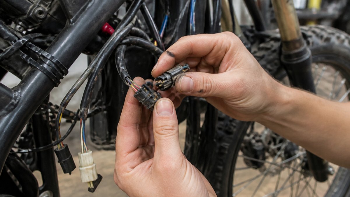
Locate the throttle connector at the base of the grip or where the cable meets the handlebar stem.
If pins look clean and straight, reconnect firmly until you hear or feel a click. If the throttle now works, the problem was a loose connection.
If pins are corroded, gently rub a pencil eraser over each to remove surface corrosion, then reconnect and test.
Step 3: How to Test an E-Bike Throttle with a Multimeter
A multimeter is the most useful tool for separating a bad throttle from a bad controller, brake sensor, or wiring fault. This step gives a repeatable test sequence with expected readings.
Reconnect the battery only for the voltage tests below, keep the bike on a stable surface with the wheel grounded, and never let the motor spin while your hands are near the drivetrain. If you see or smell burned insulation at any point, stop and treat the harness as damaged.
Identify the throttle connector and pins
Most e-bike throttles use a 3-pin connector: supply (VCC or +5V), ground (GND), and signal (SIG); some add a fourth pin for a switch or second Hall output. Wire colors aren’t standardized, so confirm pin functions from your wiring diagram, controller label, or throttle label before probing, with no diagram, trace each wire and test in the order below.
Common connector families are JST-SM (small rectangular, often 3-pin), Julet or Higo (round waterproof, 2- to 5-pin), and molded inline. Note the type before disconnecting so you can reseat it correctly.
Set up the meter
Set the meter to DC voltage (autorange or 20V). Insert the black probe in COM and the red in V. Back-probe from the wire side with thin tips or sewing pins so you don’t spread the terminals; if sealed, use the exposed wire just behind the plug.
Test 1: Supply voltage (VCC to GND)
With the battery connected and system on, place the black probe on ground and the red on supply. A healthy supply reads about 4.5V to 5.5V DC on most systems. If you read 0V, the controller isn’t supplying the throttle, check the main harness, controller connector, and any inline fuse. Well below 4.5V suggests a loaded or failing supply circuit.
Test 2: Ground continuity
With the system off and battery disconnected, set the meter to continuity or resistance. Check resistance from the throttle ground pin to a known good ground such as the controller ground or battery negative. A good ground reads near 0 ohms (typically under 1 ohm). Tens or hundreds of ohms, or no continuity, indicates a broken ground path, reseat connectors and inspect the harness before replacing parts.
Test 3: Signal voltage sweep (SIG to GND)
Reconnect the battery and power on. Place the black probe on ground and the red on the signal pin. Note the reading at rest, then slowly twist or press the throttle through full travel while watching the meter.
Expected behavior on a typical Hall-effect throttle:
- At rest: approximately 0.8V to 1.2V (some models rest near 0V; both patterns exist).
- At full throttle: approximately 4.0V to 4.8V.
- The voltage should rise smoothly and proportionally as the throttle moves, with no dead spots and no jumps.
Pass/fail decisions:
- Smooth rise from rest to full and back: the throttle signal is healthy. Move on to the brake cut-off and controller checks.
- Stuck at rest voltage with no change: the throttle or its signal wire is faulty. Inspect the signal pin and wire run, then replace the throttle if the wire is intact.
- Stuck at full voltage: a shorted signal wire or a failed sensor. Disconnect the throttle and recheck; if the reading persists with the throttle unplugged, the short is in the harness.
Test 4: Quick controller-input cross-check
If the throttle passes all three tests but the motor still doesn’t respond, the fault is downstream: the controller isn’t acting on a valid input, or a brake cut-off is overriding it. Proceed to the brake sensor test before condemning the controller, this ordered approach prevents replacing a good throttle when a brake sensor was the real problem.
Record your readings at rest, mid-travel, and full throttle. A written baseline makes an intermittent fault much easier to catch on a second test and gives a repair shop useful data if you hand the bike off.
Use these multimeter tests in sequence to identify whether the throttle, wiring, or controller is at fault.
| Test | What to Check | Expected Result | Failure Sign |
|---|---|---|---|
| Supply voltage | VCC to GND with battery connected | 4.5V to 5.5V DC | 0V or well below 4.5V |
| Ground continuity | Throttle ground to controller ground with battery off | Near 0 ohms, typically under 1 ohm | Tens or hundreds of ohms |
| Signal sweep | Signal pin voltage through full throttle travel | Smooth rise from 0.8V-1.2V to 4.0V-4.8V | Stuck voltage, erratic jumps, or dead spots |
| Controller response | Motor engagement with brake released and throttle twisted | Motor responds to throttle input | Motor does not respond despite good throttle signal |
Step 4: E-Bike Throttle Hall Sensor Troubleshooting
Many modern e-bikes use Hall sensors inside the throttle grip to detect rotation.
A Hall sensor generates a digital signal as the throttle rotates.
Locate the Hall sensor connector, typically a small three- or four-pin connector separate from the main throttle connector.
Reconnect the Hall sensor firmly.
To confirm a faulty Hall sensor, connect your multimeter to the sensor output wire and twist the throttle slowly.
Step 5: Test the Brake Cut-Off Sensor and Controller Response
Locate the brake cut-off sensors, typically one small switch on each brake lever.
Trace the sensor wires to their connectors and wiggle each gently.
If the throttle works when you bypass the brake sensor but not in normal operation, the sensor connection is loose.
If all connectors are tight and the throttle still doesn’t respond, the controller may be faulty.
When to Replace Your Throttle Assembly or Seek Professional Help
By this point the test sequence should give a clear answer: the throttle signal is good, bad, or intermittent, and the brake cut-off and controller have been checked in order. Use the decision points below to choose between a simple fix, a part replacement, and a professional repair.
Replace the throttle assembly when
- The signal voltage does not change through the full grip travel, or it is stuck at rest or full voltage with the connector seated and the wire intact.
- The signal is erratic and the fault follows the grip or the throttle lead when you flex it.
- The housing is cracked, the grip rubs the brake lever or cable, or the return spring is broken.
Throttle assemblies are consumable parts, generally replaced rather than repaired. Match the connector type (JST-SM, Julet/Higo, or molded inline) and pin count before ordering, and confirm the rest and full-throttle voltage pattern matches your controller’s expected input.
Repair the harness or connector when
- The throttle passes its own tests but the supply or ground reading fails at the connector.
- A pin is loose in the housing, a wire is chafed at a zip tie or frame edge, or corrosion is limited to the plug.
- Cleaning the pins and reseating the connector restores a stable reading.
Harness repairs are appropriate only when the wire and connector are accessible and the damage is cosmetic or at the plug. Don’t splice into a sealed section of the main harness unless you can make a weatherproof, strain-relieved joint.
Stop and seek professional repair when
- You see charring, melted insulation, a burning smell, or heat-discolored connectors anywhere in the throttle, brake, or controller wiring. This indicates an overcurrent or short that can damage the controller or create a fire risk.
- The battery or controller shows damage, swelling, or error behavior. Battery and controller faults are not DIY territory.
- The throttle tests good, the brake cut-off tests good, and the controller still does not respond. Controller replacement and programming require model-specific tools and settings.
A note on parts and fitment
Replacement throttles vary in connector type, pin count, voltage range, and whether they include a switch or second Hall output. Order by connector and voltage pattern, not color alone. If you ride a Surron or Talaria, confirm model-year harness and controller compatibility before buying, and keep the old throttle until the new one is tested. For riders upgrading or replacing components, browse our Surron e-bike product category and review Surron e-bike performance upgrades to match parts to your specific model.
The safe rule: replace the throttle when its own signal fails, repair the harness when the fault is at the plug, and stop for professional help whenever you see heat damage, battery or controller symptoms, or a fault you cannot reproduce with a meter.
Frequently Asked Questions
Why is my electric bike throttle not working?
An electric bike throttle stops working due to loose wiring, damaged connectors, a faulty throttle assembly, brake cut-off sensor activation, or controller failure. Start by checking physical connections and the throttle grip for obstructions. If those look clean, test the throttle signal with a multimeter or check whether the brake sensor is holding the motor offline.
How do I test an e-bike throttle with a multimeter?
Set your multimeter to voltage mode and connect the probes to the throttle signal wire and ground. Twist the throttle grip slowly, voltage should increase smoothly from 0V to 5V (or your bike’s specified range). If voltage stays flat or jumps erratically, the throttle is faulty. No voltage change means a broken signal wire or damaged throttle assembly.
Can a loose wire cause an e-bike throttle to stop working?
Yes. A loose connection at the throttle connector, motor wire harness, or controller breaks the signal path. Even a partially disconnected wire can cause intermittent throttle response or complete failure. Always inspect connectors for corrosion, bent pins, or loose seating before replacing components.
What should I do if my e-bike throttle works intermittently?
Intermittent throttle response usually points to a loose connector, corroded wire, or failing Hall sensor. Disconnect and reconnect all throttle-related plugs firmly. Clean connector pins with a dry cloth. Twist the throttle while watching for dropouts, if it cuts in and out, the issue is likely electrical contact or a worn Hall sensor that needs replacement.
Throttle issues don’t have to sideline your rides. By working through these diagnostic steps methodically, you can pinpoint the exact problem and decide on the right fix. Most throttle failures stem from loose connectors or corroded pins, problems you can solve yourself in under an hour. When replacement is necessary, Supermoto wheels and tires stocks quality throttle assemblies for popular e-bike models. Get the right parts and get back on the trail.
